Connecting Rod Damages and Important Considerations
Introduction
In diesel engines certain bolts are of utmost importance. To ensure that a bolt performs its function effectively it needs to be tightened to a predetermined torque within the elastic range. This torque value is provided by the manufacturer. In some cases tightening the bolt may require multiple steps. For instance in certain bolts after tightening they may need to be loosened and tightened again to achieve the desired tension and proper clamping force.
In this article I will share some insight I’ve gained while I was trying to explore the reasons behind the “tightening, loosening, and re-tightening” steps provided in the tightening procedures by machine manufacturers.
I am quoting a significant portion of the article from a comprehensive study conducted by A. Strozzi [1] and colleagues. In the other sections I have included the sources I used as much as possible. I have also tried to add some insights from my own experiences. Any mistakes made during the process of citation are my responsibility. The valuable information and commendations are entirely the result of the efforts of the quoted authors.
The images without references belong to me. Let’s start by refreshing our knowledge about the connecting rod (con-rod). After that, we will discuss the most common damages encountered in connecting rods and finally, we will touch upon con rod bolts to conclude the article.
Connecting Rod (Con-rod)
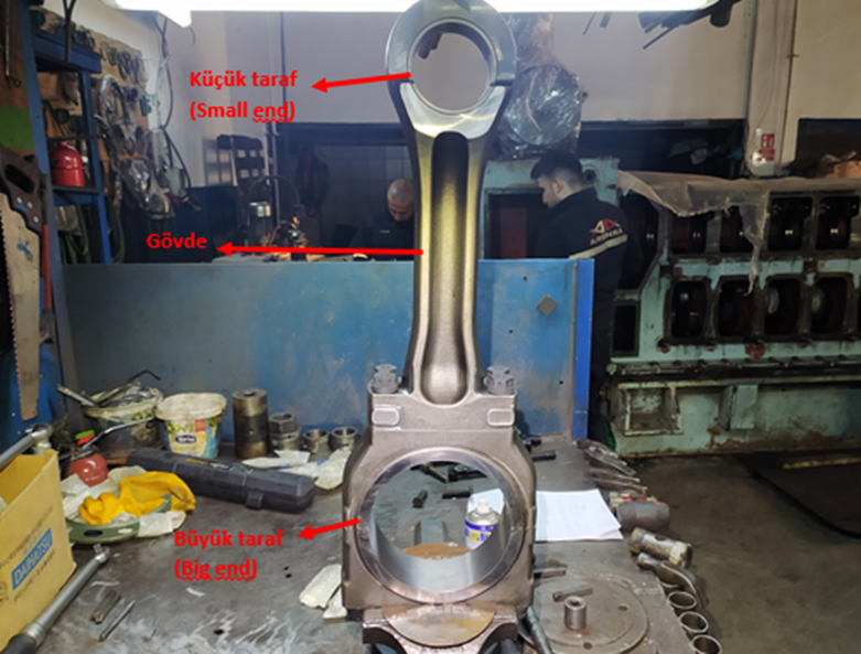
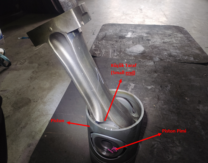
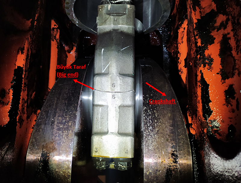
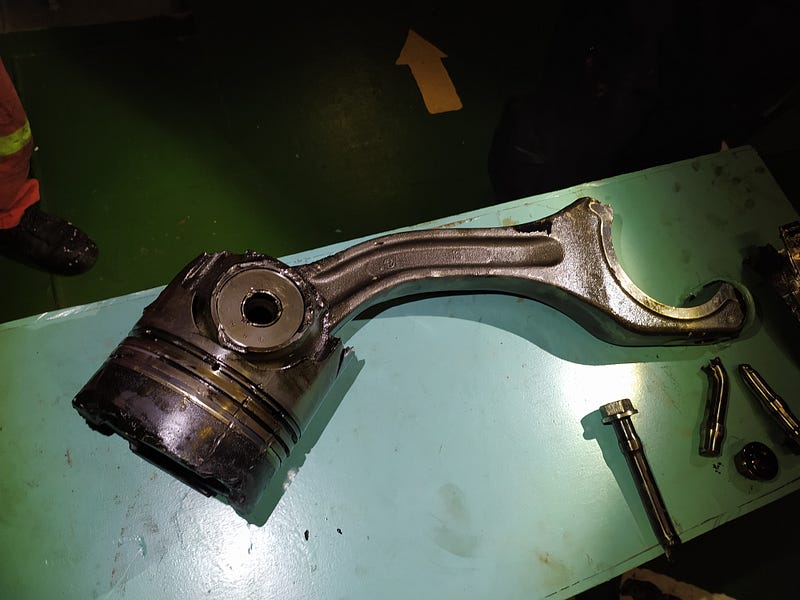
The connecting rod (con-rod) is one of the most important components used in internal combustion engines [1]. Resembling the thicker part of an I-profile sheet connecting rods link the piston and crankshaft converting the force obtained in the piston into circular motion. Connecting rods have two holes at each end one large and one small. The small end accommodates the piston pin while the big end connects to the crankpin through the connecting rod bearings.
The connecting rod is one of the components that is exposed to high-frequency fatigue loading [1]. During the design of the connecting rod the forces from the combustion gases and inertia forces acting on the rod are taken into account. It should be strong enough to withstand external loads, rigid enough to provide a solid connection and lightweight enough to minimize inertia forces [1]. Considering all these factors the connecting rod needs to be delicately designed [1].
Damages on Con-rods
1- Con-rod Shank Damages
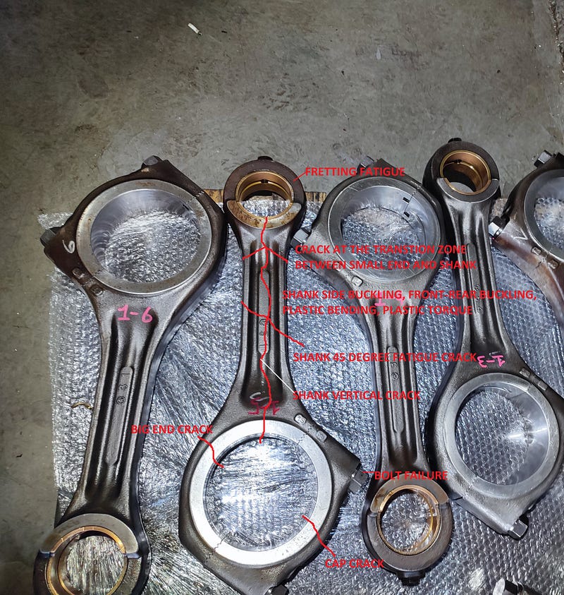
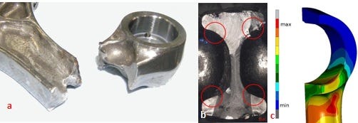
The con-rod shank is subjected to compression at the top dead center or bottom dead center when the expansion due to combustion pressure begins. Conversely during the intake stroke it is subjected to tension due to the inertia forces of the piston and piston pin mass. As a result the fatigue stresses experienced by the con-rod body are reversed [1].
The estimated stress concentrations calculated using the finite element method for the von Mises stress distribution under normal loads are shown in Figure 5-c [1]. It can be observed that the red area concentrates in the transition region between the small end and the body. The con-rod damage shown in Figure 5-a is found to be in the region of stress concentration seen by the finite element method [1]. Figure 5-b shows four crack initiation regions, indicating fatigue fractures under normal loading conditions [1].
The differences in geometry between the small end, big end, and body — the first two parts being circular, and the body being beam-shaped — lead to variations in stresses and inevitable stress concentration regions [1], [2]. In addition to the damages that may occur under normal loading conditions, the damages observed under excessive compression conditions in the con-rod are shown in Figure 6 [1].
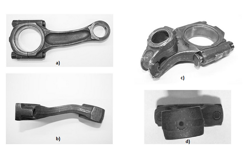
The mentioned damages occur as a result of events such as a seizure in the engine due to insufficient lubrication or the entry of cooling water into the combustion chamber, preventing the piston stroke. Figure 6a shows side buckling, 6b exhibits fore-aft buckling, 6c displays the catastrophic buckling of the con-rod leading to damage in the entire engine, and 6d illustrates the image of a connecting rod subjected to plastic torque and bending.
In the relevant article [1] rare cases of transverse cracks and 45-degree cracks have also been mentioned. Since these occurrences are typically observed in high-revving engines such as racing engines I won’t elaborate on them in this context.
2- Small End Damages
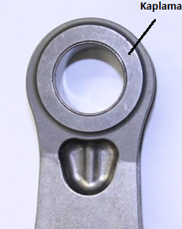
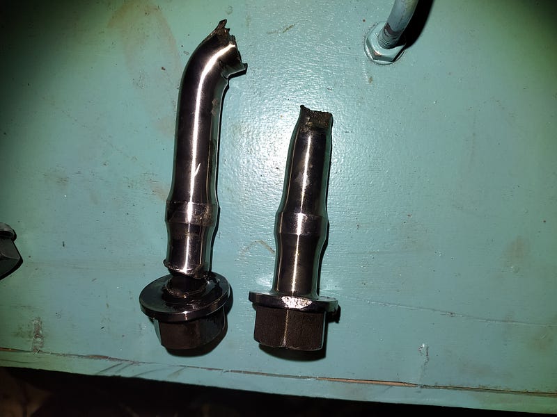
One of the common issues found in the small end of the piston con-rod is small end bush rotation. As a result of bushing rotation the lubrication channel that provides lubrication for the bushing and piston pin on the small end of the con-rod gets blocked. The blockage of the lubrication channel leads to insufficient lubrication in that area causing scoring. This scoring results in damages to the piston and piston pin. The exact cause of bushing rotation is not always clear, but it is generally attributed to vibrations.
In machine components exposed to thermomechanical cyclic loads, a phenomenon known as “microslip” is observed [2]. This phenomenon is characterized by small tangential motions accumulating at the contact interface between two assembly elements [2]. Fretting fatigue resulting from microslip has been observed in the small end of the con-rod [1]. To prevent fretting fatigue caused by microslip friction-reducing coatings are applied to con-rods to minimize the friction coefficient between the bushing and the small end aiming to mitigate this phenomenon.
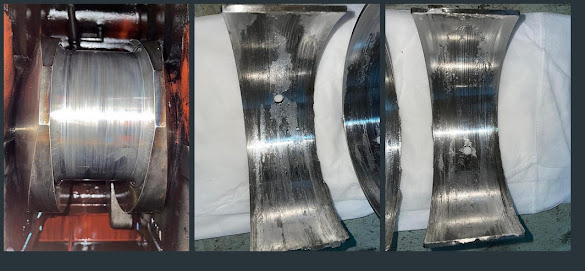
3- Big End Damages
In the big end of the piston con-rod one of the common defects similar to the small end is bearing rotation. Bearing rotation can lead to the disruption of the oil film and cause fretting failure. The big end like the small end is another section where fretting failure can occur.
4 — Con-rod Bolts
The damage occurring in con-rod bolts can lead to destructive consequences. Despite significant advancements in bolt mechanics, issues related to bolt failure can still be encountered. Factors contributing to these problems include under-tightening of bolts with less torque than required or contrary to manufacturer’s instructions, design errors, material or fabrication defects [3].
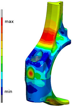
Studies conducted on con-rod bolts have reported that very high tightening torques result in excessively high bolt preload leading to over-tightening and inducing high stress concentrations especially in neighboring bolt holes particularly when combined with poor design [4]. Additionally they pointed out that local bending effects can cause early con-rod fatigue [4], [5].
In the literature it is emphasized that bolted connections should be tightened to a sufficient torque that provides an adequate amount of preload [3], [5], [6]. As the preload increases the stress amplitude transferred to the bolt decreases [5]. It has been indicated that one of the significant factors affecting bolt behavior in the con-rod is the preload [3], [4]. Excessive preload can lead to fatigue and fretting damage on the con-rod while low preload can cause stress amplitudes that may result in bolt fatigue and damage [3], [4].
Speaking more generally con-rod bolts are crucial components that require maximum attention. These parts have been designed and carefully engineered by the machine manufacturer with established procedures and the use of appropriate materials. Following the manufacturer’s guidelines (instruction books) for tightening and using original parts is essential to avoid catastrophic events in the machine. Factors such as lubrication in specified threads (or the use of protective, anti-seize sprays/chemicals recommended by the manufacturer) and precise adherence to the tightening procedures (tightening, loosening, and re-tightening) significantly influence the bolt’s preloading. The friction coefficient and multiple tightening processes — tightening, loosening, and re-tightening — affect these forces [5]. Even seemingly small details like improper lubrication in the wrong places can shorten the service life of the machine.
Conclusion
In conclusion connecting rods play a crucial role in the machine and are not easily damaged. However in my personal opinion these parts’ Achilles’ heel is the con-rod bolts. These components should be treated with care replaced when their working hours/limits are reached and genuine spares should be used when replacing. Additionally in the manufacturer’s instructions even though some steps may seem impractical it should be noted that they are based on calculations, work and experiments of a team with valuable experiences and therefore the procedure should be carefully followed.
Thank you for your valuable time and patience.
Sources
[1] A. Strozzi, A. Baldini, M. Giacopini, E. Bertocchi, and S. Mantovani, “A repertoire of failures in connecting rods for internal combustion engines, and indications on traditional and advanced design methods,” Eng. Fail. Anal., vol. 60, pp. 20–39, 2016, doi: https://doi.org/10.1016/j.engfailanal.2015.11.034.
[2] N. Antoni, Q.-S. Nguyen, J.-L. Ligier, P. Saffré, and J. Pastor, “On the cumulative microslip phenomenon,” Eur. J. Mech., vol. 26, no. 4, pp. 626–646, 2007.
[3] S. Griza, F. Bertoni, G. Zanon, A. Reguly, and T. R. Strohaecker, “Fatigue in engine connecting rod bolt due to forming laps,” Eng. Fail. Anal., vol. 16, no. 5, pp. 1542–1548, 2009.
[4] L. Witek and P. Zelek, “Stress and failure analysis of the connecting rod of diesel engine,” Eng. Fail. Anal., vol. 97, pp. 374–382, 2019.
[5] D. Croccolo, M. De Agostinis, S. Fini, G. Olmi, L. Paiardini, and F. Robusto, “Tribological properties of connecting rod high strength screws improved by surface peening treatments,” Metals (Basel)., vol. 10, no. 3, p. 344, 2020.
[6] V. 2230, “Systematische Berechnung hochbeanspruchter Schraubenverbindungen — Zylindrische Einschraubenverbindungen,” 2003.


Yorumlar
Yorum Gönder