Case Study: Crankpin Bearing Seizure
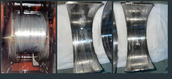
To investigate the seizure of the crankpin bearing in generator No. 3 of a ship operating we conducted an on-site inspection aboard the ship to identify the root cause. The information provided was as follows:
- Disassembly and reassembly of covers and pistons are performed for maintenance purposes.
- After maintenance, the machinery is reassembled.
- The machine is started and operated for a continuous duration of 15 minutes.
- Engine connecting rod axial movement is inspected by opening the crankcase covers.
- An issue of overheating or failure is observed in crankpin bearing No. 1.
 |
| Figure 1 - From left to right - No. 1 crankpin, No. 1 upper crankpin bearing, No. 1 lower crankpin bearing |
 | ||||
| Figure 2 - Example Demonstration of Connecting Rod Measurement |
 |
| Figure 3 - Connecting Rod Measurement Points |
 |
| Figure 4 -No 1 Crankpin polishing |
For accurate hardness measurement, the surface needs to be cleaned first. To achieve this, a polishing process is performed using sandpaper with progressively finer grits, ranging from coarse to fine particles.
 |
| Figure 5 -No 1 Crankpin Hardness Measurement |
Investigating the cause of these incidents and how the ovality occurred led us to the conclusion that a small but significant detail had been overlooked. The manufacturer places a mark on the both connecting rod and connecting rod cap when they leave the factory. These marks should be in the same direction, and each cylinder's cap should be connected to its corresponding rod. Through inspections, it was determined that the caps of cylinder 1 and cylinder 2 had been swapped. As a result of this mix-up ovality was detected in the rods.
 |
| Figure 6 - Direction of Set Marks as Shown in the Manufacturer's Manual [1] |
Incorrectly attaching the caps causes high ovality, which in turn leads to the disruption of the oil film and the resulting lack of lubrication. This results in elevated temperatures and damage to both interacting surfaces.
 |
| Figure 7 - Mismatched Marks on Cap and Connecting Rod (2–1 and 2–2, 2–1 should have been mounted on 2–1) |
During the assembly of machinery, it's crucial to carefully read and follow the manufacturer's instructions. Rushing through tasks should be avoided. If possible, seeking consultation or advisory services from the manufacturer can help prevent such situations from occurring in the first place.
Source
[1] — Yanmar 8N21 Instruction Book
Yorumlar
Yorum Gönder